Difference between revisions of "DS18B20"
(Add schematic) |
|||
| Line 3: | Line 3: | ||
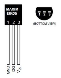
==Pinout== | ==Pinout== | ||
[[File:Ds18b20-pinout.jpg|200px]] [http://www.hobbytronics.co.uk/ds18b20-arduino DS18B20 Image found here] | [[File:Ds18b20-pinout.jpg|200px]] [http://www.hobbytronics.co.uk/ds18b20-arduino DS18B20 Image found here] | ||
| − | |||
==Resources== | ==Resources== | ||
| − | + | ===[https://en.wikipedia.org/wiki/1-Wire 1-Wire] at wikipedia.=== | |
==Raspberry Pi== | ==Raspberry Pi== | ||
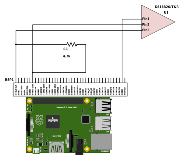
| − | + | ==Schematic== | |
| + | [[File:Rpi2-DS18B20.png|600px]] | ||
| + | ==Code== | ||
<source lang="text"> | <source lang="text"> | ||
# add this line to /boot/config.txt | # add this line to /boot/config.txt | ||
Revision as of 15:18, 4 May 2017
DS18B20
Contents
DS18B20
Pinout
Resources
1-Wire at wikipedia.
Raspberry Pi
Schematic
Code
# add this line to /boot/config.txt
dtoverlay=w1-gpio

modprobe w1-gpio
modprobe w1-therm

# device directory
cd /sys/bus/w1/devices
ls -l
# cd to your unique DS18B20 identifier
cat w1_slave
Resources

