Difference between revisions of "Thermo Numitron Clock"
(initial creation) |
(made table for award. One contest. ;-)) |
||
| (3 intermediate revisions by the same user not shown) | |||
| Line 2: | Line 2: | ||
| − | My Thermo Numitron Clock is an evolving learning experiment. It's based on the old school circa 1960s Numitron display. In this case an IV-9 which can be driven by low voltage in my case about 4.2VDC. This is unlike VFD and Nixie tubes that take a considerable higher DC voltage in the range of a minimum of ~ 40VDC to approaching ~ 200VDC. It is the first PCB I've designed and sent out for fabrication. I've done several PCBs for other projects at home using toner transfer but I wanted to try a fabrication house as my projects evolve. I used OSH Park to create three (3) boards delivered for ~$20 bucks. Although I created the board several years ago I only recently configured the project to be [https://oshpark.com/profiles/jhalbrecht shared via this link.] One design problem in the hardware was easily fixed in Software. I have to switch the two bytes representing the pair of nibbles for each two tubes. That is looking from left to right I have to enter the | + | My Thermo Numitron Clock is an evolving learning experiment. It's based on the old school circa 1960s Numitron display. In this case an IV-9 which can be driven by low voltage in my case about 4.2VDC. This is unlike VFD and Nixie tubes that take a considerable higher DC voltage in the range of a minimum of ~ 40VDC to approaching ~ 200VDC. It is the first PCB I've designed and sent out for fabrication. I've done several PCBs for other projects at home using toner transfer but I wanted to try a fabrication house as my projects evolve. I used OSH Park to create three (3) boards delivered for ~$20 bucks. Although I created the board several years ago I only recently configured the project to be [https://oshpark.com/profiles/jhalbrecht shared via this link.] One design problem in the hardware was easily fixed in Software. I have to switch the two bytes representing the pair of nibbles for each two tubes. That is looking from left to right I have to enter the left two digits before the right. |
The IV-9 sub assembly uses a single DM74LS47N, BCD to 7-Segment Decoder/Driver with | The IV-9 sub assembly uses a single DM74LS47N, BCD to 7-Segment Decoder/Driver with | ||
| Line 19: | Line 19: | ||
[[File:HomeAmationUWP.PNG|600px]] | [[File:HomeAmationUWP.PNG|600px]] | ||
| + | [[File:ThermoNumitronClockWithUWP.JPG|600px]] | ||
| + | |||
| + | ==honors, accolades, contests and self promotion== | ||
| + | "... I'd like to thank the Academy..." | ||
| + | {| class="wikitable" | ||
| + | |+Contests - Awards | ||
| + | |- | ||
| + | |Contest | ||
| + | |[https://blog.adafruit.com/2014/02/10/beaglebone-black-case-contest-first-round-of-winners-week-1-beagleboneblackcase-txinstruments-beagleboardorg/ BeagleBone Black case contest] | ||
| + | |} | ||
| + | |||
| + | |||
| + | |||
| + | |||
| + | [[Category:HomeAmation]] | ||
Latest revision as of 10:33, 28 January 2019
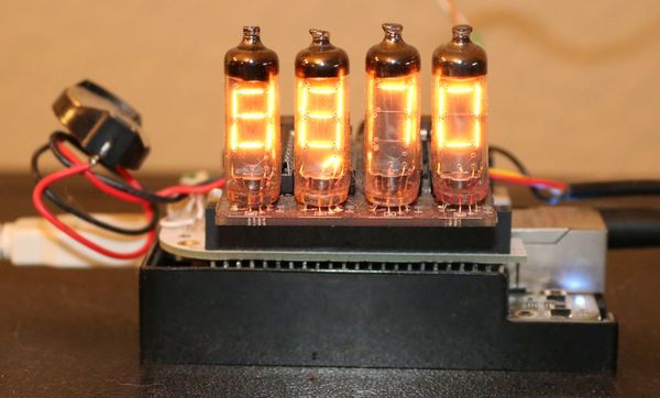
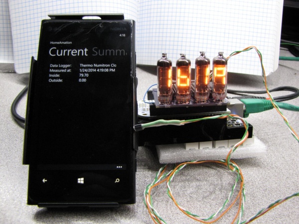
Thermo Numitron Clock of my own design displays time and temperature and can communicate via MQTT
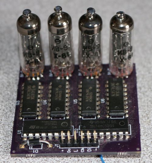
My Thermo Numitron Clock is an evolving learning experiment. It's based on the old school circa 1960s Numitron display. In this case an IV-9 which can be driven by low voltage in my case about 4.2VDC. This is unlike VFD and Nixie tubes that take a considerable higher DC voltage in the range of a minimum of ~ 40VDC to approaching ~ 200VDC. It is the first PCB I've designed and sent out for fabrication. I've done several PCBs for other projects at home using toner transfer but I wanted to try a fabrication house as my projects evolve. I used OSH Park to create three (3) boards delivered for ~$20 bucks. Although I created the board several years ago I only recently configured the project to be shared via this link. One design problem in the hardware was easily fixed in Software. I have to switch the two bytes representing the pair of nibbles for each two tubes. That is looking from left to right I have to enter the left two digits before the right.
The IV-9 sub assembly uses a single DM74LS47N, BCD to 7-Segment Decoder/Driver with Open-Collector Outputs, display drivers per tube. A pair of 74HC595N, 8-bit shift register with tri-state output registers, to clock in the four (4) nibbles of BCD data to the decoder chips. I brought out the O output pin so that these boards could be daisy chained for larger displays.
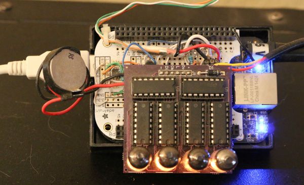
I built a custom cape for a BeagleBone Black linux SBC. It has inputs currently configured for two DS18B20 digital thermometers. One for inside and another for outside temperature. There is also an DS1307 RTC hence the coin battery and a retrofit transistor to drive a decimal point on the IV-9 that isn't supported by the 74LS47.
I originally had a nodejs server serving XML to that my HomeAmation project could read the temperature. Later as I learned about MQTT I wrote a python app to serve up the time and temperature via MQTT to a Mosquitto broker I have running at home. See my MQTT page on this wiki.
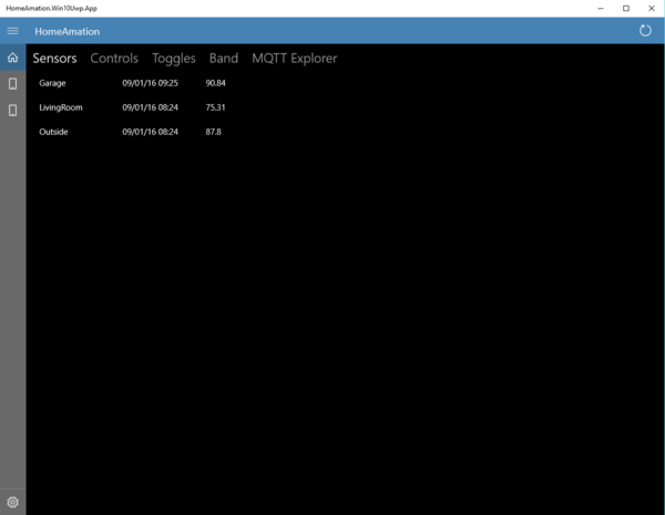
This is a screen shot of my HomeAmation UWP app running under windows 10. It shows the inside and outside temperature from the ThermoNumitron Clock as well as the temperature in the garage being served by a RaspberryPi. The control tab if selected in the app allows me to control lighting in my home.
honors, accolades, contests and self promotion
"... I'd like to thank the Academy..."
| Contest | BeagleBone Black case contest |
