Difference between revisions of "BoeDuino-Bot.Net"
(Added links to blog posts. Introduction to Dottie, and PCB creation.) |
|||
| Line 4: | Line 4: | ||
<h4>First prototype</h4> | <h4>First prototype</h4> | ||
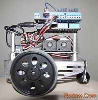
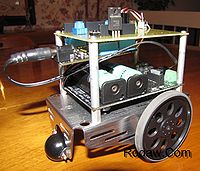
[[File:Dottie0.jpg|200px|thumb|none|BoeDuinoBot.Net Dottie]] | [[File:Dottie0.jpg|200px|thumb|none|BoeDuinoBot.Net Dottie]] | ||
| + | Read this first blog post [http://www.rodaw.com/nerding/dottie-boeduinobot-net/ introducing dottie]. | ||
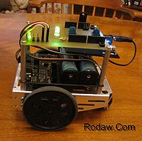
<h4>BoeDuino-Bot.Net v1.0</h4> | <h4>BoeDuino-Bot.Net v1.0</h4> | ||
| Line 12: | Line 13: | ||
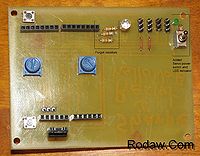
[[File:BoeDuino-Bot.NetV1.0TopWM.jpg|200px|thumb|none|BoeDuino-Bot.Net PCB Top]] | [[File:BoeDuino-Bot.NetV1.0TopWM.jpg|200px|thumb|none|BoeDuino-Bot.Net PCB Top]] | ||
| − | Note the addition of resistors and servo power switch and LED indicator. | + | Note the addition of resistors and servo power switch and LED indicator added after PCB etch. |
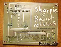
[[File:BoeDuino-Bot.NetV1.0BottomWM.jpg|200px|thumb|none|BoeDuino-Bot.Net PCB Bottom]] | [[File:BoeDuino-Bot.NetV1.0BottomWM.jpg|200px|thumb|none|BoeDuino-Bot.Net PCB Bottom]] | ||
Revision as of 10:38, 28 November 2011
Contents
BoeDuino-Bot.Net
ServoCentering
First prototype
Read this first blog post introducing dottie.
BoeDuino-Bot.Net v1.0
{{#ev:youtube|vtDHHEG7DwY}}
PCB Circuit board
Note the addition of resistors and servo power switch and LED indicator added after PCB etch.
